Note
Go to the end to download the full example code.
Extrusion and fragmentation modes
This example demonstrates the qtcad.builder.Builder.extrude operation
and the different strategies that are available when merging new
objects into the existing geometry (see
qtcad.builder.FragmentationMode) on the example of a smiling
face.
Initialization
from qtcad.builder import Builder, MeshAlgorithm3D
from qtcad.builder import Mask, Polygon
Initializing the Builder
Below, we initialize a new instance of qtcad.builder.Builder and load the
shapes we’ll later user from an OASIS layout. An overview of the
currently registered masks and shapes can be obtained through
qtcad.builder.Builder.print_mask_tree(). We then select all masks and thus all
shapes in all masks and visualize them using
qtcad.builder.Builder.view_shapes().
- Builder.load_layout(file_path: str | Path, cell_name: str | None = None, name_property: str = 'name', plot_when_fail: bool = False, cache: bool = True, path_tolerance: float | None = None) Self
[⚡ Utility] Read the cell named
cell_name(default is the top cell) from aGDSor anOASISfilefile_pathand parse its structure. Each layer will become aMaskappropriately named and the ID from the layout file (provided there are no conflicting IDs) containing polygons for each shape found in the layer. The name of each shape is taken from the user propertyname_property. The length units in the file are assumed to be10**length_unit_exponentmeters (default is nanometres).- Parameters:
file_path – The path to the
GDSorOASISfile.cell_name – The name of the cell that the device is specified in. If
None, use the top cell.name_property – The user property that contains the name of a shape.
plot_when_fail – Whether to show debugging plots when the parsing of the imported shapes fails. Currently these plots will show polygons whose hull and holes cannot be differentiated.
path_tolerance – Tolerance used when converting paths to polygons (smaller = more points).
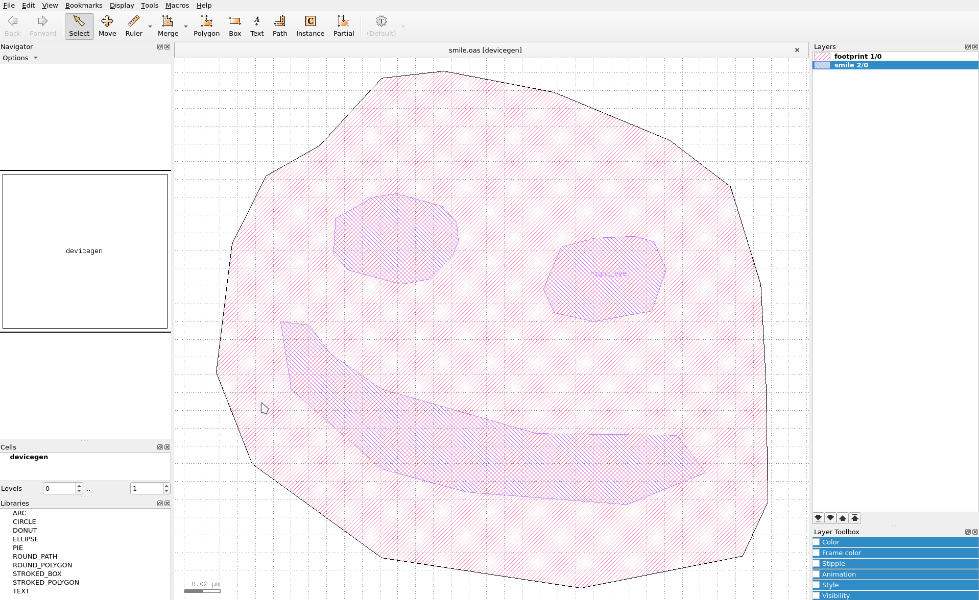
Fig. 18 The photomask layout for the smiling face.
builder = (
    Builder()
    .load_layout("./layouts/smile.oas")
    .print_mask_tree()
    .use_all_masks()
    .view_shapes(
        save="figs/shapes_in_mask.svg",
        font_size=20,
    )
)

[15:25:46] INFO     Loading layout from cache                           misc.py:266
                    /home/hiro/.cache/qtcad/builder/layout_81b718d3fc80
                    f7ba952a6a2af4b5e620aad1f3566effb66f7b572da7713de5f
                    5_None_name_None_-9.pkl
           INFO     Adding mask 'footprint' from cache                 masks.py:750
           INFO     Adding mask 'smile' from cache                     masks.py:750
Layout
├── Mask 1 "footprint"
│   └── 0  Polygon  "footprint"
└── Mask 2 "smile"
    ├── 0  Polygon  "left_eye"
    ├── 1  Polygon  "right_eye"
    └── 2  Polygon  "mouth"
           INFO     Using mask 'footprint-smile' (implicitly         builder.py:801
                    selecting shapes [Polygon 0 'footprint', Polygon
                    1 'left_eye', Polygon 2 'right_eye', Polygon 3
                    'mouth'])
           INFO     Viewing shapes: [Polygon 0 'footprint', Polygon builder.py:1987
                    1 'left_eye', Polygon 2 'right_eye', Polygon 3
                    'mouth'] using a temporary builder instance
The shape names are either read from a user property (name by
default) or from text labels (as is the case for the right_eye
here).
Building the geometry
Next, select the mask "footprint" (the outline of the smiling
face) extrude that mask to create a volume. We used
qtcad.builder.Builder.set_mesh_size to set the mesh characteristic length
and qtcad.builder.Builder.set_mesh_size to tell the Builder not to
try and lower the mesh size based on the resulting volume size. We
use qtcad.builder.Builder.differentiate_hull_surfaces with the argument
False to make sure all the hull surfaces get the same name.
- Builder.extrude(height: float) Self
[🏗️ Operation] Create a solid extrusion of a plane shape of height
heightat the currentz_coordinate. Also advances the currentz_coordinatebyheight. The resulting surfaces are automatically named using the current naming strategy by appending unique suffixes.- Parameters:
height – The distance by which the shape will be extruded into three dimensional space.
(
    builder.set_mesh_size(10)
    .set_min_elements(1)
    .differentiate_hull_surfaces(False)
    .use_mask("footprint")
    .set_z(-10)
    .extrude(20)
)
[15:25:47] INFO     Using mask 'footprint' (implicitly selecting     builder.py:801
                    shapes [Polygon 0 'footprint'])
           INFO     Setting z-coordinate to -10                      builder.py:903
           INFO     Extruding shape 0 from mask 'footprint' with    builder.py:2794
                    name 'footprint' by 20 at z=-10
           INFO     Creating new physical group with name           builder.py:2580
                    'footprint_hull'
           INFO     Creating new physical group with name           builder.py:2580
                    'footprint'
           INFO     Setting z-coordinate to 10                       builder.py:903

<qtcad.builder.builder.Builder object at 0x75dd41c3cb90>
The above results in a volume named footprint (named after the shape).
builder.view(
    surfaces=False,
    volume_labels=True,
    angles=(-45, 0, 45),
    save="figs/extrusion_foot.svg",
    font_size=20,
    surface_labels=False,
)

           INFO     Saving figure                                   builder.py:1926

<qtcad.builder.builder.Builder object at 0x75dd41c3cb90>
The extrusion advances the current z-coordinate to the top of the extruded volume.
print(builder.get_z())
10
The surfaces of created by the extrusion operation are automatically added to physical groups named according to the volume:
builder.view(
    surfaces=True,
    volume_labels=False,
    surface_labels=True,
    angles=(-45, 0, 45),
    save="figs/extrusion_foot_surfs.svg",
    font_size=20,
)

           INFO     Saving figure                                   builder.py:1926

<qtcad.builder.builder.Builder object at 0x75dd41c3cb90>
Displace mode
Next, we insert the left eye using qtcad.builder.Builder.displace_mode (the
default mode). Note that we used qtcad.builder.Builder.set_z to set the
base coordinate of the extrusion and qtcad.builder.Builder.use_shape to
select a specific shape in the mask to extrude. By default selecting
a mask also selects all shapes in the masks for subsequent operation
(see for example Adding the gate surfaces in the
Gated Quantum Dot tutorial). We
also use qtcad.builder.Builder.set_mesh_size to set a finer mesh size for
subsequently created volumes. We re-enable hull surface differ with
the argument True.
- Builder.displace_mode(dim: int | list[int] | None = None) Self
[🔧 Modifier] When creating new entities, override the physical groups where the new entities intersect with the old ones to correspond to the physical group of the new elements.

- Parameters:
dim – See
use_mode.
(
    builder.set_mesh_size(5)
    .use_mask("smile")
    .set_z(0)
    .displace_mode()
    .differentiate_hull_surfaces(True)
    .use_shape("left_eye")
    .extrude(20)
)
[15:25:48] INFO     Using mask 'smile' (implicitly selecting shapes  builder.py:801
                    [Polygon 0 'left_eye', Polygon 1 'right_eye',
                    Polygon 2 'mouth'])
           INFO     Setting z-coordinate to 0                        builder.py:903
           INFO     Selected shapes: [Polygon 0 'left_eye']          builder.py:854
           INFO     Extruding shape 0 from mask 'smile' with name   builder.py:2794
                    'left_eye' by 20 at z=0
           INFO     Creating new physical group with name           builder.py:2580
                    'left_eye_bottom'
           INFO     Creating new physical group with name           builder.py:2580
                    'left_eye_side'
           INFO     Creating new physical group with name           builder.py:2580
                    'left_eye_top'
           INFO     Creating new physical group with name           builder.py:2580
                    'left_eye_hull'
           INFO     Fragmenting...                                fragmenter.py:218
[15:25:49] INFO     Creating new physical group with name           builder.py:2580
                    'left_eye'
           INFO     Setting z-coordinate to 20                       builder.py:903

<qtcad.builder.builder.Builder object at 0x75dd41c3cb90>
The resulting volume intersects with the the footprint. Because we
chose the displace mode the resulting fragments are all added to the
physical group left_eye (name generated from the shape name, see
also qtcad.builder.Builder.set_group_name(), qtcad.builder.Builder.group_from_mask(),
and qtcad.builder.Builder.group_from_shape()).
builder.view(
    surfaces=False,
    volume_labels=True,
    surface_labels=False,
    angles=(-45, 0, 45),
    save="figs/extrusion_left_eye.svg",
    font_size=20,
)

           INFO     Saving figure                                   builder.py:1926

<qtcad.builder.builder.Builder object at 0x75dd41c3cb90>
Note that the hull surfaces are now differentiated into bottom, side, and top.
builder.view(
    surfaces=False,
    volume_labels=False,
    surface_labels=True,
    groups=["left_eye"],
    angles=(-45, 0, 45),
    font_size=5,
    save="figs/extrusion_left_eye_surfs.svg",
)

           INFO     Saving figure                                   builder.py:1926

<qtcad.builder.builder.Builder object at 0x75dd41c3cb90>
Fill mode
Next, we will use qtcad.builder.Builder.fill_mode to add the right eye. The
fill mode is the conceptual opposite of the displace mode:
- Builder.fill_mode(dim: int | list[int] | None = None) Self
[🔧 Modifier] When creating new entities, inherit the physical groups where the new entities intersect with the old ones.

- Parameters:
dim – See
use_mode.
We also demonstrate here qtcad.builder.Builder.number_hull_surfaces to
number the hull surfaces consecutively according to the direction
they are facing in addition of naming them according to their
position (bottom, side, top). This is useful, for example, to apply
boundary conditions only to select surfaces:
builder.set_z(0).fill_mode().number_hull_surfaces().use_shapes("right_eye").extrude(30)
[15:25:50] INFO     Setting z-coordinate to 0                        builder.py:903
           INFO     Selected shapes: [Polygon 1 'right_eye']         builder.py:854
           INFO     Extruding shape 1 from mask 'smile' with name   builder.py:2794
                    'right_eye' by 30 at z=0
           INFO     Creating new physical group with name           builder.py:2580
                    'right_eye_bottom'
           INFO     Creating new physical group with name           builder.py:2580
                    'right_eye_side[0]'
           INFO     Creating new physical group with name           builder.py:2580
                    'right_eye_side[1]'
           INFO     Creating new physical group with name           builder.py:2580
                    'right_eye_side[2]'
           INFO     Creating new physical group with name           builder.py:2580
                    'right_eye_side[3]'
           INFO     Creating new physical group with name           builder.py:2580
                    'right_eye_side[4]'
           INFO     Creating new physical group with name           builder.py:2580
                    'right_eye_side[5]'
           INFO     Creating new physical group with name           builder.py:2580
                    'right_eye_side[6]'
           INFO     Creating new physical group with name           builder.py:2580
                    'right_eye_side[7]'
           INFO     Creating new physical group with name           builder.py:2580
                    'right_eye_side[8]'
           INFO     Creating new physical group with name           builder.py:2580
                    'right_eye_side[9]'
           INFO     Creating new physical group with name           builder.py:2580
                    'right_eye_top'
           INFO     Creating new physical group with name           builder.py:2580
                    'right_eye_hull'
           INFO     Fragmenting...                                fragmenter.py:218
           INFO     Creating new physical group with name           builder.py:2580
                    'footprint_bottom'
           INFO     Creating new physical group with name           builder.py:2580
                    'footprint_side'
           INFO     Creating new physical group with name           builder.py:2580
                    'footprint_top'
           INFO     Creating new physical group with name           builder.py:2580
                    'right_eye'
           INFO     Setting z-coordinate to 30                       builder.py:903

<qtcad.builder.builder.Builder object at 0x75dd41c3cb90>
We find, this results in the part of the geometry intersecting with
the "footprint" volume inherit the physical group of that volume.
builder.view(
    surfaces=False,
    volume_labels=True,
    surface_labels=False,
    angles=(-45, 0, 45),
    save="figs/extrusion_right_eye.svg",
    font_size=20,
)

builder.view(
    surfaces=False,
    volume_labels=False,
    surface_labels=True,
    groups=["right_eye"],
    angles=(-45, 0, 45),
    font_size=5,
    save="figs/extrusion_right_eye_surfs.svg",
)


           INFO     Saving figure                                   builder.py:1926
[15:25:51] INFO     Saving figure                                   builder.py:1926

<qtcad.builder.builder.Builder object at 0x75dd41c3cb90>
Overlay mode
Finally, we will use qtcad.builder.Builder.overlay_mode to add the right
eye. The overlay mode is a middle ground between displacing and filling.
- Builder.overlay_mode(dim: int | list[int] | None = None) Self
[🔧 Modifier] Like
fill_mode, but instead of inheriting the group from the intersecting entities the intersecting elements will be added to physical groups named like[intersecting_group].[new_entity_group].
- Parameters:
dim – See
use_mode.
(
    builder.set_z(0)
    .differentiate_hull_surfaces(False)
    .overlay_mode()
    .use_shapes("mouth")
    .extrude(30)
)
           INFO     Setting z-coordinate to 0                        builder.py:903
           INFO     Selected shapes: [Polygon 2 'mouth']             builder.py:854
           INFO     Extruding shape 2 from mask 'smile' with name   builder.py:2794
                    'mouth' by 30 at z=0
           INFO     Creating new physical group with name           builder.py:2580
                    'mouth_hull'
           INFO     Fragmenting...                                fragmenter.py:218
[15:25:52] INFO     Creating new physical group with name           builder.py:2580
                    'footprint.mouth_hull'
           INFO     Creating new physical group with name           builder.py:2580
                    'footprint.mouth'
           INFO     Creating new physical group with name           builder.py:2580
                    'footprint_hull.mouth'
           INFO     Creating new physical group with name 'mouth'   builder.py:2580
           INFO     Setting z-coordinate to 30                       builder.py:903

<qtcad.builder.builder.Builder object at 0x75dd41c3cb90>
We find, this results in the part of the geometry intersecting with
the "footprint" volume to be named "footprint.mouth".
builder.view(
    surfaces=False,
    volume_labels=True,
    surface_labels=False,
    angles=(-45, 0, 45),
    save="figs/extrusion_mouth.svg",
    font_size=20,
)

           INFO     Saving figure                                   builder.py:1926

<qtcad.builder.builder.Builder object at 0x75dd41c3cb90>
When viewing just the mouth, we can make out how the new volume and surfaces are named.
builder.view(
    surfaces=True,
    volume_labels=False,
    surface_labels=True,
    angles=(-45, 0, 45),
    save="figs/extrusion_mouth_only.svg",
    font_size=10,
    groups=["mouth", "footprint.mouth"],
)

           INFO     Saving figure                                   builder.py:1926

<qtcad.builder.builder.Builder object at 0x75dd41c3cb90>
The final mesh then becomes:
builder.mesh(algorithm3d=MeshAlgorithm3D.HXT)

builder.view(
    surfaces=False,
    volume_labels=True,
    surface_labels=False,
    angles=(-45, 0, 45),
    save="figs/extrusion_mesh.png",
    font_size=20,
)
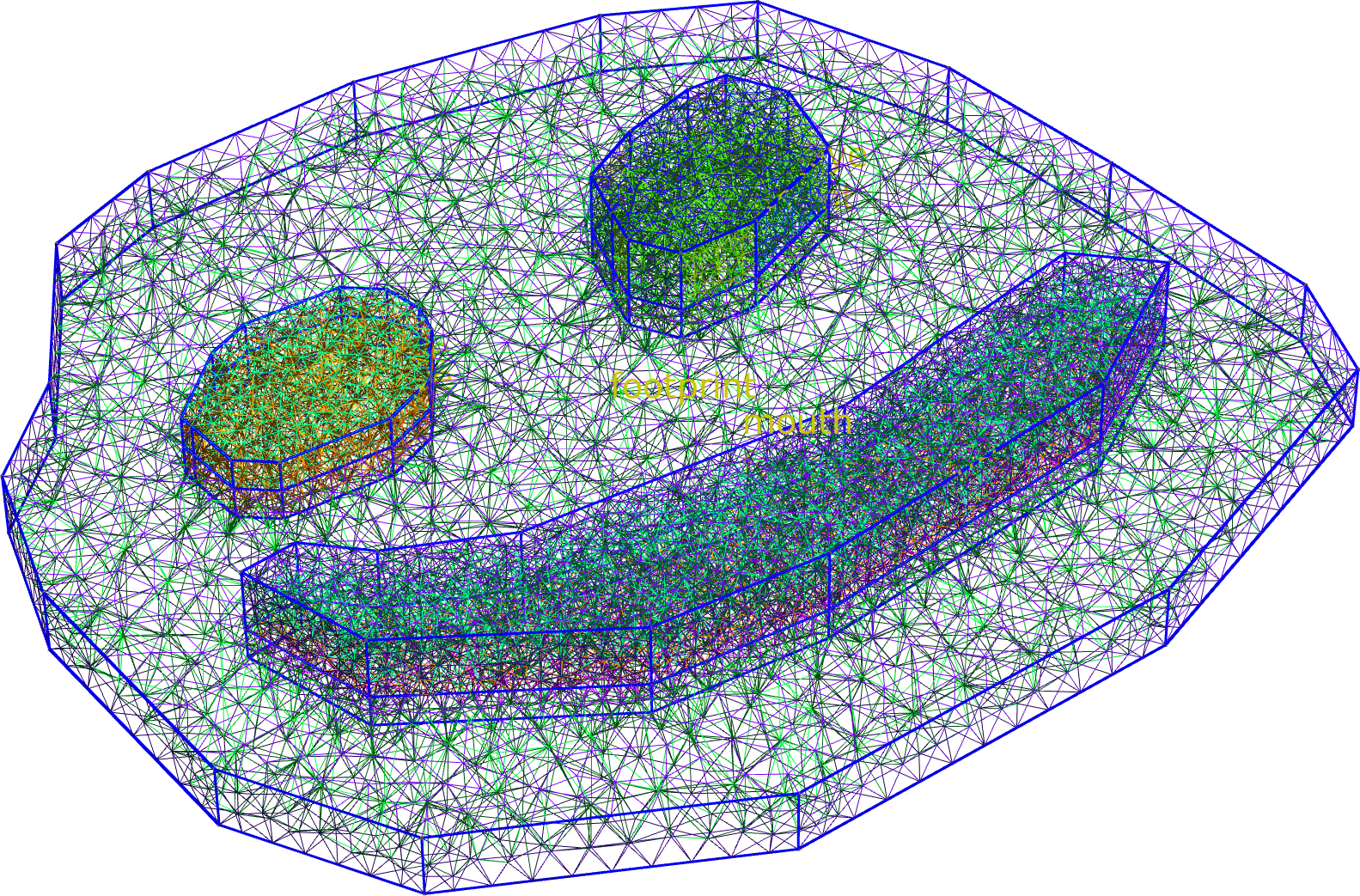
[15:25:53] INFO     Preparing to mesh                               builder.py:1561
           INFO     Detecting appropriate random factor             builder.py:3681
           INFO     Random factor is now appropriate                builder.py:3705
           INFO     Meshing                                         builder.py:1577
[15:25:54] INFO     Checking mesh conformity                        builder.py:3767
           INFO     Writing                                         builder.py:1663
                    ../../../../../../../../../../../tmp/tmpwpj9r1o
                    j/mesh.msh
[15:25:56] INFO     Checking connectivity                           builder.py:3794

nodes:   0%|          | 0/7189 [00:00<?, ?it/s]
nodes:   0%|          | 0/7189 [00:00<?, ?it/s]
nodes:   0%|          | 0/7189 [00:00<?, ?it/s]
nodes: 100%|██████████| 7189/7189 [00:00<00:00, 38090.44it/s]
nodes: 100%|██████████| 7189/7189 [00:00<00:00, 38058.71it/s]
nodes: 100%|██████████| 7189/7189 [00:00<00:00, 38040.03it/s]
           INFO     Saving figure                                   builder.py:1926

<qtcad.builder.builder.Builder object at 0x75dd41c3cb90>
Filling around the entire model
Fill mode is also usefull to add material around an existing structure. To that end we first create a container shape that is slightly larger than the bounding box of the existing geometry. We then add that shape as a mask and use fill mode to extrude it around the existing geometry.
container = (
    Polygon.from_bbox(*builder.bbox, name="container").scaled(1.2).translated(-2, 0)
)
container_mask = Mask("container")
container_mask.add_shape(container)

(
    builder.clear_mesh()
    .add_mask(container_mask)
    .inherit_mesh_size()
    .fill_mode()
    .set_z(-21)
    .extrude(60)
    .view(
        surfaces=False,
        volume_labels=True,
        surface_labels=False,
        angles=(-45, 0, 45),
        save="figs/extrusion_container.svg",
        font_size=20,
    )
)

[15:25:57] INFO     Clearing mesh                                   builder.py:1522
           INFO     Setting z-coordinate to -21                      builder.py:903
           INFO     Extruding shape 0 from mask 'container' with    builder.py:2794
                    name 'container' by 60 at z=-21
           INFO     Creating new physical group with name           builder.py:2580
                    'container_hull'
           INFO     Fragmenting...                                fragmenter.py:218
[15:26:01] INFO     Creating new physical group with name           builder.py:2580
                    'container'
           INFO     Setting z-coordinate to 39                       builder.py:903
           INFO     Saving figure                                   builder.py:1926

<qtcad.builder.builder.Builder object at 0x75dd41c3cb90>
When we view the just-created volume in isolation, we see that the existing geometry has been “stenciled out”.
(
    builder.view(
        surfaces=False,
        volume_labels=True,
        surface_labels=False,
        angles=(-45, 0, 45),
        save="figs/extrusion_container_only.svg",
        font_size=20,
        groups=["container"],
    )
)

# Local Variables:
# jinx-languages: "en_CA"
# End:

           INFO     Saving figure                                   builder.py:1926

<qtcad.builder.builder.Builder object at 0x75dd41c3cb90>
Total running time of the script: (0 minutes 15.326 seconds)