1. Mesh generation using QTCAD® Builder
1.1. Requirements
1.1.1. Software components
QTCAD
1.1.2. Python script
qtcad/examples/practical_application/Tunnel_Falls_DAPS/1-tunnel_falls_builder.py
1.1.3. References
1.2. Briefing
This tutorial uses Builder to construct a
three-dimensional model of a Tunnel Falls
[GMkadzikH+25, MEB+25, NZW+24] double quantum
dot in a \(\mathrm{Si}/\mathrm{SiGe}\) heterostructure. In this layout,
the upper qubit-row electrodes are finger gates: narrow gates that extend from
the upper gate row toward the active channel. The B finger gates act as
barrier gates, while the P finger gates act as plunger gates.
Rather than reproducing the full 12-dot chip (see Fig. 1 (a) of
[MEB+25]), the script isolates the P5–P6 neighborhood and
includes the electrodes that shape its confinement landscape: the outer barrier finger
gates B4 and B6, the interdot barrier finger gate B5, the two plunger finger
gates P5 and P6, the buried screening gate SG, and the center-screening gate
CS. This reduced model is small enough for fast finite-element meshing
while remaining large enough to analyze the resulting double dot and extract
physical quantities relevant to detuning axis pulsed spectroscopy (DAPS).
The name CS is a modeling label used to distinguish the central screening
gate from the buried screening gate SG. When comparing against the
device-layout in Fig. 1 (a) of [MEB+25], both of these
screening gates indicated with the SG label. To allow different voltages to be
applied to each of these gates, we use different labels here.
The vertical stack used in the model is based on the reported Tunnel Falls
heterostructure [GMkadzikH+25, MEB+25]. The
\(4.6\,\mathrm{nm}\) Si quantum-well thickness is taken directly from
[MEB+25]. The remaining layers and their vertical dimensions are
chosen within the ranges reported in [GMkadzikH+25]. From bottom
to top, the simplified geometry contains a relaxed
\(\mathrm{Si}_{0.7}\mathrm{Ge}_{0.3}\) buffer slice, a strained
\(\mathrm{Si}_{0.972}\mathrm{Ge}_{0.028}\) quantum well, an upper relaxed
\(\mathrm{Si}_{0.7}\mathrm{Ge}_{0.3}\) barrier, a Si cap, a two-layer
\(\mathrm{SiO}_2/\mathrm{HfO}_2\) gate oxide, the buried SG surface, an
\(\mathrm{SiO}_2\) interlayer dielectric, and finally the upper finger-gate
and CS surfaces.
The script saves the mesh and geometry files as
meshes/tunnel_falls_double_dot.mshmeshes/tunnel_falls_double_dot.xao
It also uses view and
view_shapes to save the Builder
snapshots under output/tunnel_falls_builder/ without opening persistent
visualization windows.
1.3. Setup
1.3.1. Header
We begin by importing the necessary Python modules:
from pathlib import Path
from qtcad.builder import Builder, Mask, Polygon
The Builder object constructs the
three-dimensional geometry. Mask stores
two-dimensional layout layers, and Polygon is
used to create the shapes that make up those masks.
The basic idea of how three-dimensional device models are built using the
Builder class is to start with a set of
two-dimensional masks, situated in the \(xy\) plane, each representing
certain features of the device.
These masks are then extruded along the \(z\) axis to form the volumetric
regions of the device, with care being taken to ensure that overlapping
regions are assigned the correct names.
Next, we define where the generated mesh, geometry, and
Builder figure files will be written:
script_dir = Path(__file__).parent.resolve()
mesh_dir = script_dir / "meshes"
mesh_dir.mkdir(parents=True, exist_ok=True)
path_out = script_dir / "output"
path_local_out = path_out / "tunnel_falls_builder"
path_local_out.mkdir(parents=True, exist_ok=True)
1.3.2. Constants
Next, we define length scales that will be used in our model device. These parameters can be altered to produce devices with the same topology but different physical dimensions.
We start with mesh characteristic lengths:
# Mesh controls ---------------------------------------------------------------
char_len = 20.0
dot_char_len = 10.0
The global characteristic mesh length is char_len. The smaller
dot_char_len is later applied only to the dot region, where the quantum-dot
wavefunctions are expected to be localized.
The script also defines Builder figure generation
parameters:
# Builder figure controls -----------------------------------------------------
save_builder_figures = True
view_angles = (-58.0, 20.0, 38.0)
top_view_angles = (0.0, 0.0, 90.0)
By default, the practical-application script saves visualization snapshots
through Builder’s internal save option while closing the Gmsh view
immediately. This keeps the workflow non-interactive. To skip the figure
generation in headless or batch runs, run the script with
save_builder_figures = False.
The view_angles and top_view_angles tuples define the Euler angles that
determine the viewing perspective of the three-dimensional geometry and the
two-dimensional layout, respectively.
1.3.3. Lateral dimensions
The lateral dimensions are written near the top of the script so that the reduced geometry can be adjusted easily:
# Lateral dimensions (nm) -----------------------------------------------------
# x follows the gate row / transport direction. y points from the
# center-screening side toward the finger-gate side.
#
# References:
# - Marcks et al., Nat. Commun. 16, 11381 (2025).
# - George et al., Nano Lett. 25, 793-799 (2025).
# - Neyens et al., Nature 629, 80-85 (2024).
#
# The pitch is taken from the references above. The remaining
# lateral widths and distances are modeling choices chosen to approximate
# the layout of Fig. 1a of Marcks et al.
gate_pitch = 60.0
finger_length = 30.0
gate_span = 90.0
center_screen_gap = 20.0  # Gap between finger gates and central screening gate.
center_screen_width = 30.0

domain_length = 5.0 * gate_pitch
domain_width = gate_span + center_screen_gap + center_screen_width
Here, \(x\) follows the finger-gate row and transport direction, while \(y\)
points from the center-screening side toward the finger-gate side. The value
gate_pitch = 60 is the center-to-center spacing of neighboring B/P
finger gates. It is taken directly from the optimized 12-quantum-dot Tunnel
Falls devices reported in [NZW+24], and is also the gate
pitch of the Tunnel Falls 12-spin-qubit array discussed in
[GMkadzikH+25]. The relative placement of the B/P finger
gates, the buried SG gate, and the CS gate follow the device-layout
figures in [GMkadzikH+25, MEB+25].
The other lateral dimensions in this simplified model are not reported as exact
numbers in those papers. In particular, finger_length, gate_span,
center_screen_gap, and center_screen_width are modeling choices intended to
approximate the gate geometry as closely as possible from the available references.
The total domain dimensions are then derived from those choices and the
literature gate pitch.
The finger-gate row is pinned to the \(+y\) edge of the footprint:
# The finger-gate row starts at the +y edge of the footprint.
qubit_row_y = 0.5 * (domain_width - gate_span)
The center-screening gate is pinned to the opposite, \(-y\), edge:
# The center-screening gate ends at the opposite (-y) edge of the footprint.
center_screen_length = domain_length
center_screen_y = -0.5 * (domain_width - center_screen_width)
The buried screening gate is modeled as one continuous gate below the finger-gate row:
# The buried screening gate is one continuous gate below the finger gates.
screening_length = domain_length
screening_span = gate_span - 2.0 * finger_length
screening_row_y = qubit_row_y + 0.5 * (gate_span - screening_span)
Finally, the dot regions are positioned between the inner edges of SG and
CS:
# The dot regions are pinned between the SG-facing and CS-facing edges.
screening_inner_edge_y = screening_row_y - 0.5 * screening_span
center_screen_inner_edge_y = center_screen_y + 0.5 * center_screen_width
dot_bottom_edge_y = center_screen_inner_edge_y
dot_top_edge_y = screening_inner_edge_y
dot_width = dot_top_edge_y - dot_bottom_edge_y
dot_row_y = 0.5 * (dot_top_edge_y + dot_bottom_edge_y)
Each dot region extends from the edge of an outer barrier gate to the \(x = 0\) plane:
# Dot regions extend from the edge of an outer barrier gate to the x = 0 plane.
dot_outer_edge_x = 2.0 * gate_pitch - 0.5 * finger_length
dot_length = dot_outer_edge_x
dot_center_offset = 0.5 * dot_length
1.3.4. Vertical dimensions
The vertical stack is defined by the following thicknesses:
# Vertical dimensions (nm) ----------------------------------------------------
# References:
# - Marcks et al., Nat. Commun. 16, 11381 (2025), Fig. 1b and device-modeling
#   text: 4.6 nm Si0.972Ge0.028 quantum well in bulk Si0.7Ge0.3.
# - George et al., Nano Lett. 25, 793-799 (2025), Fig. 2 process flow:
#   30-75 nm SiGe barrier, 1-2 nm Si cap, and 5-10 nm SiO2 + 5-10 nm HfO2.
# - Neyens et al., Nature 629, 80-85 (2024): optimized 60 nm-pitch Tunnel
#   Falls devices including a 50 nm SiGe barrier variant.
#
# The relaxed buffer and interlayer dielectric are not specified in the
# references above.
relaxed_buffer_slice_thick = 50.0
quantum_well_thick = 4.6
upper_barrier_thick = 50.0
si_cap_thick = 1.0
gate_oxide_sio2_thick = 5.0
gate_oxide_hfo2_thick = 5.0
screening_ild_thick = 5.0
The vertical dimensions mix direct literature values and choices within reported process ranges:
quantum_well_thick = 4.6is taken directly from the Tunnel Falls heterostructure used in [MEB+25], which models a \(4.6\,\mathrm{nm}\) \(\mathrm{Si}_{0.972}\mathrm{Ge}_{0.028}\) quantum well embedded in \(\mathrm{SiGe}\).upper_barrier_thick = 50.0follows the \(50\)-nm-barrier Tunnel Falls variant discussed in [NZW+24]. This value also lies inside the \(30\)–\(75\,\mathrm{nm}\) \(\mathrm{SiGe}\) barrier range mentioned in [GMkadzikH+25].si_cap_thick = 1.0is chosen from the \(1\)–\(2\,\mathrm{nm}\) \(\mathrm{Si}\)-cap range reported in [GMkadzikH+25].gate_oxide_sio2_thick = 5.0andgate_oxide_hfo2_thick = 5.0are each chosen from the lower end of the \(5\)–\(10\,\mathrm{nm}\) ranges reported for the \(\mathrm{SiO}_2/\mathrm{HfO}_2\) gate-oxide stack in [GMkadzikH+25].relaxed_buffer_slice_thick = 50.0andscreening_ild_thick = 5.0are not meant to represent experimentally reported layer thicknesses. Instead they keep the finite-element problem compact while preserving the ordering of the material stack.
Finally, we also allow the dot refinement volumes to extend a small distance into the \(\mathrm{SiGe}\) barriers surrounding the quantum well:
# The dot refinement volumes extend only slightly into the adjacent SiGe.
dot_sige_extension = 6.0
This extension is not meant to redefine the whole heterostructure, and it is not a layer thickness taken from the references. It is simply a way to include a portion of the barrier regions in the dot volumes to account for leakage of the wavefunctions into these regions when solving the Schrödinger equation.
1.3.5. Helper functions
Before building the geometry, the script defines a small cleanup helper:
def remove_unwanted_surfaces(builder: Builder) -> None:
    """Remove intermediate 2D surface labels while preserving named gates.

    Args:
        builder: Builder containing the current geometry.
    """
    for layer_name in [
        "relaxed_buffer",
        "quantum_well",
        "upper_barrier",
        "si_cap",
        "gate_oxide_sio2",
        "gate_oxide_hfo2",
        "screening_ild",
        "dot_",
    ]:
        builder.dissolve_physical_group(
            lambda group, layer_name=layer_name: (
                group.dim == 2 and layer_name in group.name
            )
        )
To remain flexible, Builder creates many intermediate
surface labels while extruding volumes. Most of these surfaces are not useful as
physical groups for the Tunnel Falls geometry. This helper removes those intermediate
layers and dot surfaces from the list of physical surfaces while preserving the named
gate boundaries. We stress that the mesh itself is unaffected by this helper.
Two additional helpers save the mask layout and the three-dimensional model
only when save_builder_figures = True:
def save_shapes_if_enabled(builder: Builder, file_name: str) -> None:
    """Save selected masks in a top-down view when figures are enabled.

    Args:
        builder: Builder containing the selected masks to save.
        file_name: Name of the image file to save in ``path_local_out``.
    """
    if save_builder_figures:
        builder.view_shapes(
            save=path_local_out / file_name,
            show=False,
            angles=top_view_angles,
            font_size=16,
        )

def save_model_if_enabled(
    builder: Builder,
    file_name: str,
    *,
    show_mesh_faces: bool = False,
) -> None:
    """Save the 3D model in Gmsh when figures are enabled.

    Args:
        builder: Builder containing the model to save.
        file_name: Name of the image file to save in ``path_local_out``.
        show_mesh_faces: Whether to show mesh faces in the saved image.
    """
    if save_builder_figures:
        builder.view(
            surface_labels=True,
            volume_labels=True,
            angles=view_angles,
            save=path_local_out / file_name,
            show=False,
            font_size=16,
            show_mesh_faces=show_mesh_faces,
        )
When save_builder_figures is False, the visualization calls are skipped;
when it is True, Builder saves the requested snapshots through its internal save
argument.
1.4. Creating the masks
With the device dimensions and utility functions defined, we can now translate
the reduced lateral layout described above into
Builder masks.
Many mask shapes below are written using chained calls such as
Polygon.box(...).centered().translated(x0, y0). A
Polygon.box(width, height) is first created with its lower-left corner at
\((0,0)\). The centered method returns a copy of that polygon whose
barycenter is moved to the origin. The translated method then returns a
second copy shifted by the input values in the lateral plane. Thus, for a
centered rectangle, translated(x0, y0) places the rectangle center at
\((x_0,y_0)\).
The first mask is the simulation footprint:
# Masks -----------------------------------------------------------------------
footprint_mask = Mask("footprint")
footprint_mask.add_shape(
    Polygon.box(domain_length, domain_width, name="footprint").centered()
)
This rectangle defines the lateral size of the simulated portion of the device. It is used to extrude every layer of the simplified heterostructure.
Next, we create the buried screening-gate mask:
screening_mask = Mask("screening_gate")
screening_mask.add_shape(
    Polygon.box(screening_length, screening_span, name="SG")
    .centered()
    .translated(0.0, screening_row_y)
)
The gate name SG will become the physical boundary name used later when
applying the screening-gate voltage in the QTCAD
Device object.
The center-screening gate is built in the same way:
center_screen_mask = Mask("center_screen_gate")
center_screen_mask.add_shape(
    Polygon.box(center_screen_length, center_screen_width, name="CS")
    .centered()
    .translated(0.0, center_screen_y)
)
The upper finger gates are collected in a single mask:
finger_gate_mask = Mask("finger_gates")
finger_gate_mask.add_shapes(
    [
        Polygon.box(finger_length, gate_span, name="B4")
        .centered()
        .translated(-2.0 * gate_pitch, qubit_row_y),
        Polygon.box(finger_length, gate_span, name="P5")
        .centered()
        .translated(-1.0 * gate_pitch, qubit_row_y),
        Polygon.box(finger_length, gate_span, name="B5")
        .centered()
        .translated(0.0, qubit_row_y),
        Polygon.box(finger_length, gate_span, name="P6")
        .centered()
        .translated(gate_pitch, qubit_row_y),
        Polygon.box(finger_length, gate_span, name="B6")
        .centered()
        .translated(2.0 * gate_pitch, qubit_row_y),
    ]
)
The individual polygon names B4, P5, B5, P6, and B6 are
kept so that each gate becomes an independently addressable boundary condition
in the electrostatic problem.
Finally, the dot mask contains the left and right dot refinement regions:
dot_mask = Mask("dots")
dot_mask.add_shapes(
    [
        Polygon.box(dot_length, dot_width, name="dot_left")
        .centered()
        .translated(-dot_center_offset, dot_row_y),
        Polygon.box(dot_length, dot_width, name="dot_right")
        .centered()
        .translated(dot_center_offset, dot_row_y),
    ]
)
The "dots" mask will be extruded to define physical subdomains that will later be
used to build a double-dot SubDevice for the
Schrödinger calculation.
1.5. Building the device
1.5.1. Setting up the Builder
After the masks have been defined, we create the
Builder object and set the global mesh size:
# Setup builder ---------------------------------------------------------------
builder = Builder(name="Tunnel Falls DAPS")
builder.set_mesh_size(char_len)
Here, set_mesh_size sets the
characteristic mesh length that will be used for newly created geometry unless
a later step overrides it.
We then add all masks to Builder:
builder.add_mask(
    footprint_mask
).add_mask(
    screening_mask
).add_mask(
    center_screen_mask
).add_mask(
    finger_gate_mask
).add_mask(
    dot_mask
)
Adding a mask with add_mask registers
the two-dimensional layout layer with Builder.
It does not yet create any three-dimensional geometry.
The masks are saved as a top-down view before any three-dimensional extrusion is performed:
builder.use_all_masks()
save_shapes_if_enabled(builder, "builder_mask_layout.png")
The call to use_all_masks selects every
mask at once. This is useful only for the saved mask snapshot here, because the
subsequent construction steps select the individual masks they need.
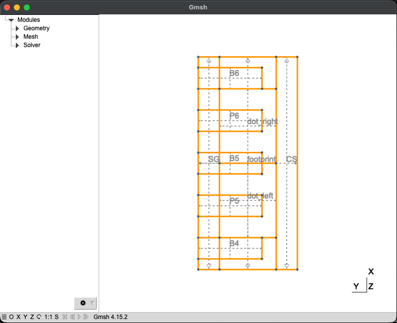
Fig. 1.5.19 Top-view mask layout used by the reduced Tunnel Falls model. The five
finger gates, the buried screening gate SG, the center-screening gate
CS, the simulation footprint, and the left/right dot regions are shown
before any three-dimensional extrusion is performed. Here SG is the
screening-gate strip near the finger gates, while CS is the central
screening gate on the opposite side of the dot channel.
1.5.2. Building the heterostructure
We start by extruding the footprint to create the relaxed \(\mathrm{SiGe}\) buffer slice:
# Build the heterostructure ---------------------------------------------------
builder.use_mask("footprint")
builder.set_group_name("relaxed_buffer").extrude(
    relaxed_buffer_slice_thick
)
The call to use_mask selects the
"footprint" mask as the lateral shape for the next construction
operation. Then, set_group_name
assigns the physical name "relaxed_buffer" to the geometry created by the
following operation. Finally,
extrude turns the selected
two-dimensional footprint into a three-dimensional volume of height
relaxed_buffer_slice_thick. This creates the lowest \(\mathrm{SiGe}\) slice of
the local Tunnel Falls model and advances the current \(z\) position to the top of
that slice.
The same footprint is then extruded to create the strained silicon quantum well:
builder.set_group_name("quantum_well").extrude(quantum_well_thick)
The upper barrier, silicon cap, and gate oxides are stacked above the quantum well:
builder.set_group_name("upper_barrier").extrude(upper_barrier_thick)
builder.set_group_name("si_cap").extrude(si_cap_thick)
builder.set_group_name("gate_oxide_sio2").extrude(gate_oxide_sio2_thick)
builder.set_group_name("gate_oxide_hfo2").extrude(gate_oxide_hfo2_thick)
Builder provides several modes that determine
how newly created surfaces or volumes are named when they intersect surfaces or volumes
that already exist. In this script, the relevant modes are the standard
displace_mode,
fill_mode, and
overlay_mode.
No explicit mode switch is needed for these first layers: they are built using
Builder’s standard
displace_mode behavior. Newly
created entities take the physical group name of the new geometry wherever
they intersect previously existing entities. This is the desired behavior for
the material stack: each newly extruded layer should remain a distinct region, rather
than inheriting the name of the layer below it.
At this point, we remove the intermediate surface labels that are not needed later:
remove_unwanted_surfaces(builder)
save_model_if_enabled(builder, "builder_heterostructure_stack.png")
The resulting stack is shown in Fig. 1.5.20.
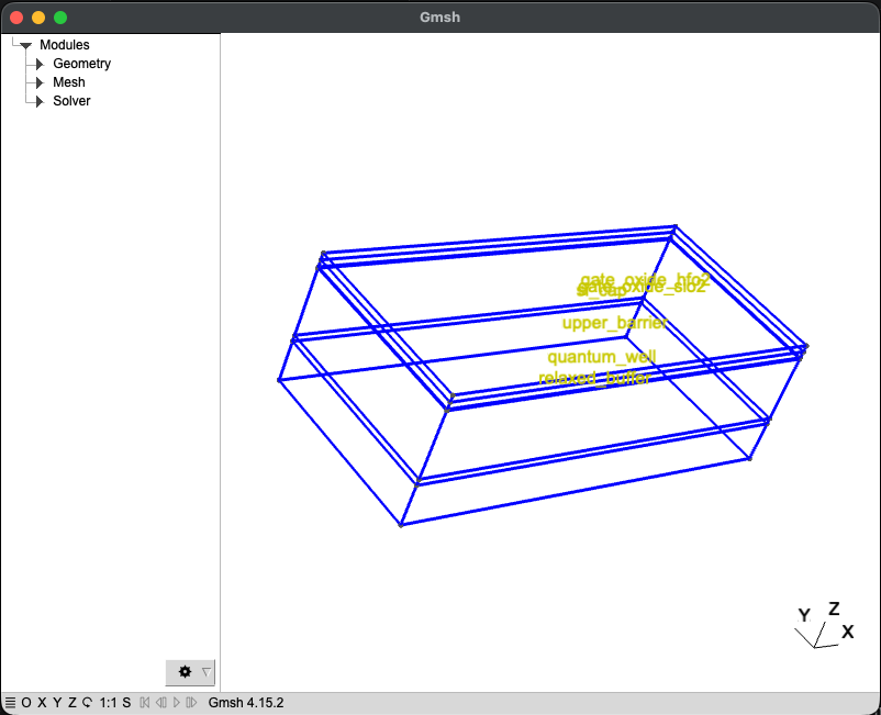
Fig. 1.5.20 Three-dimensional heterostructure after extruding the relaxed \(\mathrm{SiGe}\) buffer slice, strained quantum well, upper \(\mathrm{SiGe}\) barrier, silicon cap, and two gate oxides. At this point no metal-gate boundary surfaces has been inserted.
1.5.3. Adding the buried screening gate
The buried screening gate is inserted as a named surface before the interlayer
dielectric is added. Since no mode switch has occurred yet, the newly inserted
surface keeps the physical group name SG:
# Add the buried screening gate -----------------------------------------------
builder.use_mask("screening_gate")
builder.set_group_name("SG").add_surface()
save_model_if_enabled(builder, "builder_buried_screening_gate.png")
The add_surface method creates a
two-dimensional surface at the current \(z\) position instead of extruding a
new volume. The preceding use_mask call
selects the screening-gate mask, labeled "screening_gate", and
set_group_name labels the
surface SG.
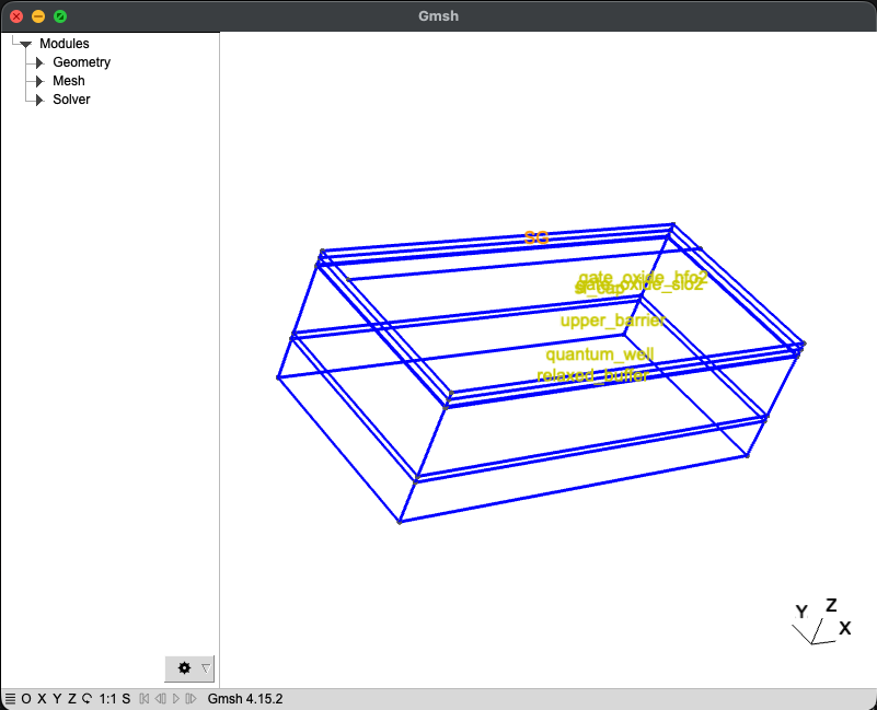
Fig. 1.5.21 The buried screening-gate surface SG inserted on top of the oxide stack.
It is added as a named surface so that the electrostatic solver can later
apply a boundary condition to it.
1.5.4. Building the interlayer dielectric
The screening gate is buried by adding an interlayer dielectric over the full footprint:
# Build the interlayer dielectric ---------------------------------------------
builder.fill_mode()
builder.use_mask("footprint")
builder.set_group_name("screening_ild").extrude(screening_ild_thick)
builder.displace_mode()
remove_unwanted_surfaces(builder)
save_model_if_enabled(builder, "builder_screening_ild.png")
The temporary call to
fill_mode is used because the
interlayer dielectric is not meant to erase the buried SG boundary
condition. In fill_mode, new geometry
inherits existing physical groups at intersections, so the previously named
SG surface remains identifiable while the dielectric fills the rest of the
footprint above it. After the dielectric is built, the script returns to
displace_mode so that later gate
surfaces can again create their own physical boundary names rather than
inheriting dielectric labels.
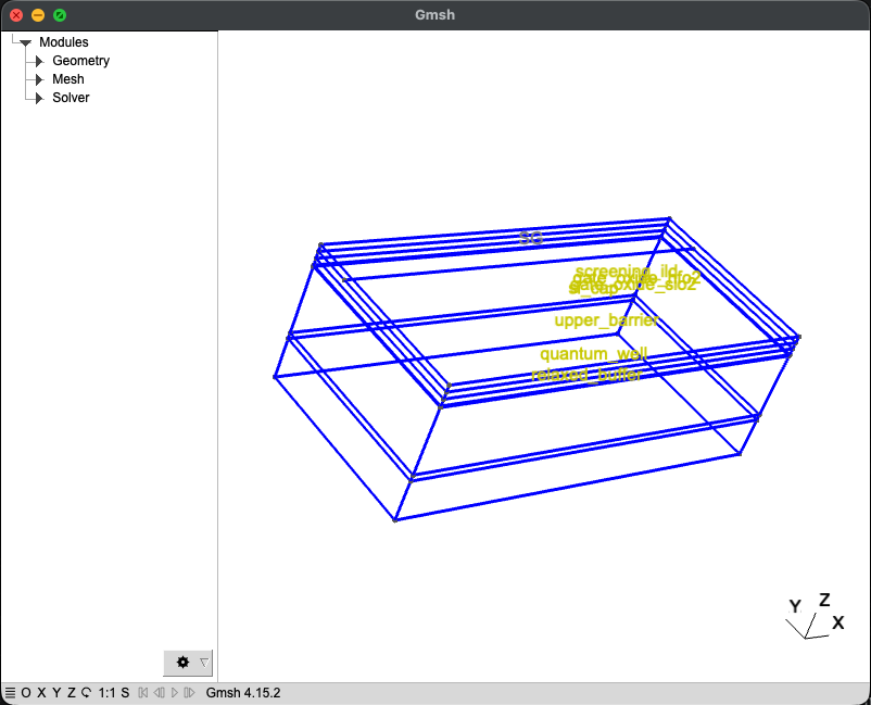
Fig. 1.5.22 Interlayer dielectric after the full footprint is extruded above the buried
screening gate. The temporary use of
fill_mode keeps the previously
inserted SG surface identifiable inside this dielectric layer.
1.5.5. Building the gates
The upper finger gates are added as physical surfaces:
# Add the upper finger gates and the center-screening gate --------------------
builder.use_mask("finger_gates")
builder.group_from_shape().add_surface()
Using group_from_shape
preserves the individual polygon names, so the final mesh contains separate
physical groups for B4, P5, B5, P6, and B6.
The center-screening gate is added in the same way:
builder.use_mask("center_screen_gate")
builder.group_from_shape().add_surface()
save_model_if_enabled(builder, "builder_upper_gates.png")
This creates the independent CS boundary condition used in the Poisson
solver.
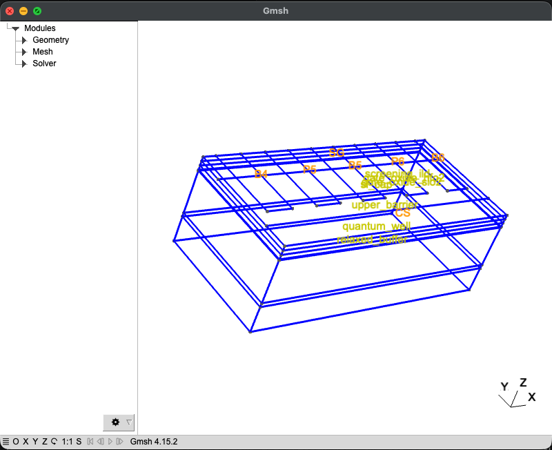
Fig. 1.5.23 Upper gate surfaces after adding the five independently biased finger gates
B4, P5, B5, P6, and B6 together with the
center-screening gate CS.
1.5.6. Building the dot regions
The last step is to create the dot regions. We consider two dot regions: one for the dot
situated below plunger gate P5 and the other for the dot situated below plunger gate
P6.
# Build the left and right dot regions ----------------------------------------
dot_stack_height = quantum_well_thick + 2.0 * dot_sige_extension

builder.overlay_mode()
builder.set_mesh_size(dot_char_len).minimum_mesh_size()
builder.set_z_from_group(
    "quantum_well",
    bottom=True,
    offset=-dot_sige_extension,
)
builder.use_mask("dots").group_from_shape().extrude(dot_stack_height)
remove_unwanted_surfaces(builder)
save_model_if_enabled(builder, "builder_dot_regions.png")
The dot regions are generated in
overlay_mode. In this mode, intersecting
regions keep track of both labels by using combined names such as
quantum_well.dot_left or upper_barrier.dot_right. Since the dot regions
extend from slightly below the quantum well to slightly above it, we will need to assign
different Materials to different subregions
of the dot region. This assignment necessitates different labels for the subregions,
which is what overlay_mode provides.
The local mesh refinement is set by calling
set_mesh_size followed by
minimum_mesh_size. This says
that the dot regions should use dot_char_len only where it is smaller than
the existing mesh size. The call to
set_z_from_group anchors the
dot extrusion to the bottom of the quantum well and shifts it down by
dot_sige_extension. This is what makes the dot subregions span the quantum
well plus a small amount of adjacent \(\mathrm{SiGe}\) instead of extending through
the entire heterostructure.
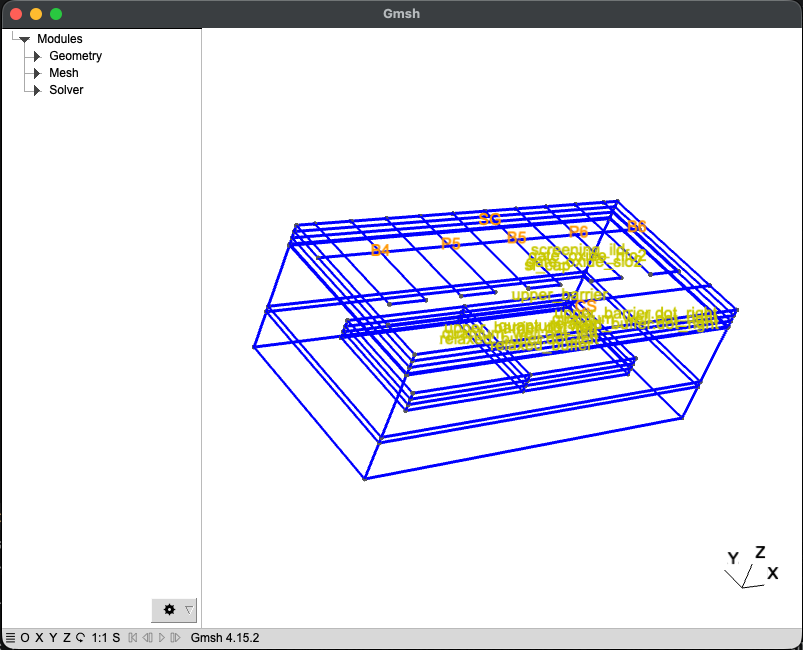
Fig. 1.5.24 Left and right dot subregions overlaid on the existing heterostructure.
1.6. Generating the mesh
Finally, the mesh is generated, a mesh snapshot is saved, and the mesh and geometry files are written to disk:
# Save the mesh ---------------------------------------------------------------
builder.mesh()
save_model_if_enabled(
    builder,
    "builder_final_mesh.png",
    show_mesh_faces=True,
)
builder.write(mesh_dir / "tunnel_falls_double_dot.msh").write(
    mesh_dir / "tunnel_falls_double_dot.xao"
)
The mesh method generates the
finite-element mesh over the completed geometry. The final
view method saves the mesh image. The
write method saves both output files:
the .msh file contains the finite-element mesh, while
the .xao file stores the geometry information required by adaptive meshing
procedures.
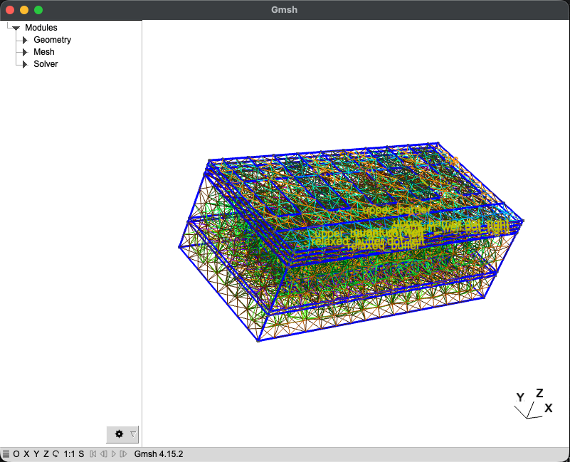
Fig. 1.6.3 Final finite-element mesh generated over the full reduced Tunnel Falls geometry. The mesh is coarse over the outer stack and refined in the dot subregions where the single-electron wavefunctions are expected to localize.
1.7. Full code
__copyright__ = "Copyright 2022-2026, Nanoacademic Technologies Inc."

from pathlib import Path
from qtcad.builder import Builder, Mask, Polygon

script_dir = Path(__file__).parent.resolve()
mesh_dir = script_dir / "meshes"
mesh_dir.mkdir(parents=True, exist_ok=True)
path_out = script_dir / "output"
path_local_out = path_out / "tunnel_falls_builder"
path_local_out.mkdir(parents=True, exist_ok=True)

# Mesh controls ---------------------------------------------------------------
char_len = 20.0
dot_char_len = 10.0

# Builder figure controls -----------------------------------------------------
save_builder_figures = True
view_angles = (-58.0, 20.0, 38.0)
top_view_angles = (0.0, 0.0, 90.0)

# Lateral dimensions (nm) -----------------------------------------------------
# x follows the gate row / transport direction. y points from the
# center-screening side toward the finger-gate side.
#
# References:
# - Marcks et al., Nat. Commun. 16, 11381 (2025).
# - George et al., Nano Lett. 25, 793-799 (2025).
# - Neyens et al., Nature 629, 80-85 (2024).
#
# The pitch is taken from the references above. The remaining
# lateral widths and distances are modeling choices chosen to approximate
# the layout of Fig. 1a of Marcks et al.
gate_pitch = 60.0
finger_length = 30.0
gate_span = 90.0
center_screen_gap = 20.0  # Gap between finger gates and central screening gate.
center_screen_width = 30.0

domain_length = 5.0 * gate_pitch
domain_width = gate_span + center_screen_gap + center_screen_width

# The finger-gate row starts at the +y edge of the footprint.
qubit_row_y = 0.5 * (domain_width - gate_span)

# The center-screening gate ends at the opposite (-y) edge of the footprint.
center_screen_length = domain_length
center_screen_y = -0.5 * (domain_width - center_screen_width)

# The buried screening gate is one continuous gate below the finger gates.
screening_length = domain_length
screening_span = gate_span - 2.0 * finger_length
screening_row_y = qubit_row_y + 0.5 * (gate_span - screening_span)

# The dot regions are pinned between the SG-facing and CS-facing edges.
screening_inner_edge_y = screening_row_y - 0.5 * screening_span
center_screen_inner_edge_y = center_screen_y + 0.5 * center_screen_width
dot_bottom_edge_y = center_screen_inner_edge_y
dot_top_edge_y = screening_inner_edge_y
dot_width = dot_top_edge_y - dot_bottom_edge_y
dot_row_y = 0.5 * (dot_top_edge_y + dot_bottom_edge_y)

# Dot regions extend from the edge of an outer barrier gate to the x = 0 plane.
dot_outer_edge_x = 2.0 * gate_pitch - 0.5 * finger_length
dot_length = dot_outer_edge_x
dot_center_offset = 0.5 * dot_length

# Vertical dimensions (nm) ----------------------------------------------------
# References:
# - Marcks et al., Nat. Commun. 16, 11381 (2025), Fig. 1b and device-modeling
#   text: 4.6 nm Si0.972Ge0.028 quantum well in bulk Si0.7Ge0.3.
# - George et al., Nano Lett. 25, 793-799 (2025), Fig. 2 process flow:
#   30-75 nm SiGe barrier, 1-2 nm Si cap, and 5-10 nm SiO2 + 5-10 nm HfO2.
# - Neyens et al., Nature 629, 80-85 (2024): optimized 60 nm-pitch Tunnel
#   Falls devices including a 50 nm SiGe barrier variant.
#
# The relaxed buffer and interlayer dielectric are not specified in the
# references above.
relaxed_buffer_slice_thick = 50.0
quantum_well_thick = 4.6
upper_barrier_thick = 50.0
si_cap_thick = 1.0
gate_oxide_sio2_thick = 5.0
gate_oxide_hfo2_thick = 5.0
screening_ild_thick = 5.0

# The dot refinement volumes extend only slightly into the adjacent SiGe.
dot_sige_extension = 6.0


def remove_unwanted_surfaces(builder: Builder) -> None:
    """Remove intermediate 2D surface labels while preserving named gates.

    Args:
        builder: Builder containing the current geometry.
    """
    for layer_name in [
        "relaxed_buffer",
        "quantum_well",
        "upper_barrier",
        "si_cap",
        "gate_oxide_sio2",
        "gate_oxide_hfo2",
        "screening_ild",
        "dot_",
    ]:
        builder.dissolve_physical_group(
            lambda group, layer_name=layer_name: (
                group.dim == 2 and layer_name in group.name
            )
        )


def save_shapes_if_enabled(builder: Builder, file_name: str) -> None:
    """Save selected masks in a top-down view when figures are enabled.

    Args:
        builder: Builder containing the selected masks to save.
        file_name: Name of the image file to save in ``path_local_out``.
    """
    if save_builder_figures:
        builder.view_shapes(
            save=path_local_out / file_name,
            show=False,
            angles=top_view_angles,
            font_size=16,
        )


def save_model_if_enabled(
    builder: Builder,
    file_name: str,
    *,
    show_mesh_faces: bool = False,
) -> None:
    """Save the 3D model in Gmsh when figures are enabled.

    Args:
        builder: Builder containing the model to save.
        file_name: Name of the image file to save in ``path_local_out``.
        show_mesh_faces: Whether to show mesh faces in the saved image.
    """
    if save_builder_figures:
        builder.view(
            surface_labels=True,
            volume_labels=True,
            angles=view_angles,
            save=path_local_out / file_name,
            show=False,
            font_size=16,
            show_mesh_faces=show_mesh_faces,
        )


# Masks -----------------------------------------------------------------------
footprint_mask = Mask("footprint")
footprint_mask.add_shape(
    Polygon.box(domain_length, domain_width, name="footprint").centered()
)

screening_mask = Mask("screening_gate")
screening_mask.add_shape(
    Polygon.box(screening_length, screening_span, name="SG")
    .centered()
    .translated(0.0, screening_row_y)
)

center_screen_mask = Mask("center_screen_gate")
center_screen_mask.add_shape(
    Polygon.box(center_screen_length, center_screen_width, name="CS")
    .centered()
    .translated(0.0, center_screen_y)
)

finger_gate_mask = Mask("finger_gates")
finger_gate_mask.add_shapes(
    [
        Polygon.box(finger_length, gate_span, name="B4")
        .centered()
        .translated(-2.0 * gate_pitch, qubit_row_y),
        Polygon.box(finger_length, gate_span, name="P5")
        .centered()
        .translated(-1.0 * gate_pitch, qubit_row_y),
        Polygon.box(finger_length, gate_span, name="B5")
        .centered()
        .translated(0.0, qubit_row_y),
        Polygon.box(finger_length, gate_span, name="P6")
        .centered()
        .translated(gate_pitch, qubit_row_y),
        Polygon.box(finger_length, gate_span, name="B6")
        .centered()
        .translated(2.0 * gate_pitch, qubit_row_y),
    ]
)

dot_mask = Mask("dots")
dot_mask.add_shapes(
    [
        Polygon.box(dot_length, dot_width, name="dot_left")
        .centered()
        .translated(-dot_center_offset, dot_row_y),
        Polygon.box(dot_length, dot_width, name="dot_right")
        .centered()
        .translated(dot_center_offset, dot_row_y),
    ]
)

# Setup builder ---------------------------------------------------------------
builder = Builder(name="Tunnel Falls DAPS")
builder.set_mesh_size(char_len)

builder.add_mask(footprint_mask).add_mask(screening_mask).add_mask(
    center_screen_mask
).add_mask(finger_gate_mask).add_mask(dot_mask)

builder.use_all_masks()
save_shapes_if_enabled(builder, "builder_mask_layout.png")

# Build the heterostructure ---------------------------------------------------
builder.use_mask("footprint")
builder.set_group_name("relaxed_buffer").extrude(relaxed_buffer_slice_thick)

builder.set_group_name("quantum_well").extrude(quantum_well_thick)

builder.set_group_name("upper_barrier").extrude(upper_barrier_thick)
builder.set_group_name("si_cap").extrude(si_cap_thick)
builder.set_group_name("gate_oxide_sio2").extrude(gate_oxide_sio2_thick)
builder.set_group_name("gate_oxide_hfo2").extrude(gate_oxide_hfo2_thick)

remove_unwanted_surfaces(builder)
save_model_if_enabled(builder, "builder_heterostructure_stack.png")

# Add the buried screening gate -----------------------------------------------
builder.use_mask("screening_gate")
builder.set_group_name("SG").add_surface()
save_model_if_enabled(builder, "builder_buried_screening_gate.png")

# Build the interlayer dielectric ---------------------------------------------
builder.fill_mode()
builder.use_mask("footprint")
builder.set_group_name("screening_ild").extrude(screening_ild_thick)
builder.displace_mode()
remove_unwanted_surfaces(builder)
save_model_if_enabled(builder, "builder_screening_ild.png")

# Add the upper finger gates and the center-screening gate --------------------
builder.use_mask("finger_gates")
builder.group_from_shape().add_surface()

builder.use_mask("center_screen_gate")
builder.group_from_shape().add_surface()
save_model_if_enabled(builder, "builder_upper_gates.png")

# Build the left and right dot regions ----------------------------------------
dot_stack_height = quantum_well_thick + 2.0 * dot_sige_extension

builder.overlay_mode()
builder.set_mesh_size(dot_char_len).minimum_mesh_size()
builder.set_z_from_group(
    "quantum_well",
    bottom=True,
    offset=-dot_sige_extension,
)
builder.use_mask("dots").group_from_shape().extrude(dot_stack_height)
remove_unwanted_surfaces(builder)
save_model_if_enabled(builder, "builder_dot_regions.png")

# Save the mesh ---------------------------------------------------------------
builder.mesh()
save_model_if_enabled(
    builder,
    "builder_final_mesh.png",
    show_mesh_faces=True,
)
builder.write(mesh_dir / "tunnel_falls_double_dot.msh").write(
    mesh_dir / "tunnel_falls_double_dot.xao"
)